(1) Roughing NC program design The purpose of roughing tool path optimization is to improve the blank removal efficiency. Generally, high-speed contouring, drilling displacement or other methods are used to design the tool path. Machining plane A, in order to avoid overcutting of the tool, select parallel milling 3D, parallel milling is used because it uses parallel scanning lines to process the model composed of multiple curved surfaces, which can be processed in one direction and two directions, and the processing efficiency is high. . Select the face milling cutter of Flat Ф18, the bottom boundary line is the contour line, and the surface A is the machined surface. Set the tool motion parameters: Select Normal in the Approach & Retract and use the system's default forward and backward contour values. To avoid the tool colliding with the blank, use absolute coordinates. The roughing allowance is 2 mm with a tolerance of 0.5 mm. In the Allow maximum machining length option in the Z direction, click on the upper right corner of the upper die and change the value to 40. By comparing the programmed simulation results with the finished final parts and representing different deviation values ​​in different colors, we can quickly know the machining results, accuracy and quality, find the overcut and the machining allowance too large, and determine Whether to use existing program commands or perform supplementary processing to achieve optimal processing results and prevent waste. Previous page
Setting the machine parameters: When the quality requirements of the workpiece can be guaranteed, in order to improve the production efficiency, a higher feed rate can be selected. In this machining, a feed rate of 1000 mm/min is used at a feed rate of 1000 mm/min.
The rough milling joint surface C, F, the face milling cutter of Flat Ф16 is used, parallel milling, the software has the function of automatically compensating the contour. For rough milling B, D, H, use the vertical milling cutter of Flat Ф 10, and select the boundary of the measuring groove as the contour line.
Rough milling cavity B, E, G, use circular milling, Flat Ф 14 flat end milling cutter. With this method, multiple curved surfaces can be processed at the same time. The infeed trajectory is carried out from the outside to the inside (or from the inside to the outside) according to the shape of the outer contour, and is especially suitable for processing planes of different heights, and the remaining blanks are relatively uniform. This is very beneficial for the latter semi-finishing and finishing. Through the CrimtronE 4.2 blank residue knowledge technology, the system will find the excess amount between the two layers during the roughing calculation of the ring milling, and automatically re-interlayer the parts, thus leaving the subsequent processing A very ideal, uniform part surface with a margin.
(2) Semi-finishing NC program design The semi-finishing method, the steps, the selected contour line and the machined surface are the same as the roughing, except that the machining allowance and roughness are selected differently.
For semi-finishing plane A, the face milling cutter of FlatФ10 is used to change the machining allowance to 0.5 mm, the tolerance is set to 0.05 mm, the feed speed is changed to 200 mm/min, and the rotation speed is changed to 1500 r/min. When semi-finishing the cavity B, E, G, Ball Ф 10 ball-end milling cutter is used, and the contour cutting knife is added. The other settings are basically the same as the roughing, and the simulated drawing is similar.
(3) Finishing NC program design Finishing tool path optimization is to improve the machining accuracy of the product. The cutting method can be selected from the positioning method, so that the horizontal and vertical profiles can be processed. In order to ensure high surface accuracy, we choose a bull nose knife. In order to shorten the machining time, we need to use a larger tool as much as possible. Here is a custom Ф6 bull nose knife.
Finishing the combined surface C, F, first geometric setting, then select the motion parameters, change the forward and backward knife to the normal direction, and change the internal height of the safety plane to the relative height, which can save the path of the knife empty knife, thus reducing Processing time.
Finishing milling cavity B, E, G, ball boring cutter of Ball Ф 6 is used, the feed speed is changed to 100 mm/min, and the rotation speed is changed to 2000 r/min. The fillet radius is set to 0.5 mm during the finish milling process and the height of the clamp is set to 100 mm, which effectively prevents the handle from interfering. The final simulation results are shown in Figure 3.
(4) Clearing the corner to create a new process, select the clearing program, Along Contour / All Area on Surface, the system will automatically analyze which areas are horizontal and which are vertical In the horizontal area, the contour is equidistantly processed, parallel cutting or ring-shaped machining, and the vertical area is processed by the contour line to realize the corner cleaning of the vertical area, and the system automatically adjusts according to the detection. According to the characteristics of the upper mold, focusing on the groove and the cavity, the parameter setting and finishing are not much different. The beef nose knife with automatic diameter Ф3 is used, and the fillet radius is 0.5 mm.
1.4 Simulation processing and inspection analysis 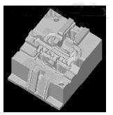
Figure 3 upper mold finishing simulation diagram
1.5 Final Program Results After getting the correct tool program, click the post-processing icon to enter Post Process to import all the processes. In the destination folder, select an output G code. Because the generated code is relatively large, because the space is limited, it will not be described.
2 Conclusion <br> <br> new generation of Cimatron E 4.2 is powerful, simple programming process, it is appropriate to grasp and use. This paper successfully used the powerful CNC machining function of Cimatron E 4.2 in the processing of MOTOROLA four-cylinder jet tube. The final generated NC code is about 6.5 Mbytes, which is about 40% higher than the original and has achieved satisfactory results. .