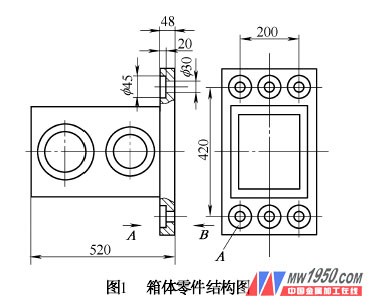
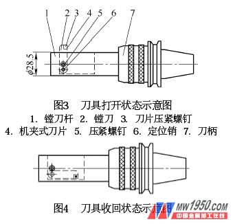
When machining 30 mm and 45 mm holes on the box parts shown in Figure 1 on a horizontal machining center, two machining schemes can be adopted due to the large difference in aperture between the two holes. Option 1: Firstly machine a 30 mm hole from the direction of the B direction, then rotate the workpiece 180° with the table, change the tool, and machine the 45 mm hole from the A direction. When machining 45 mm holes, there will be a tool bar. Long, poor processing rigidity, high tool procurement cost, and poor accuracy of two-hole coaxiality. Option 2: Infeed in the direction B of the figure. After the 30 mm hole is finished, the table does not rotate. The same direction is fed from the B direction to machine the 45 mm hole. This kind of scheme processes the above two holes, the arbor is short, the shank rigidity is good, the procurement cost is low, the processing quality and efficiency are high, but the 45 mm hole is difficult to process, and a reasonable process flow, tools and processing procedures must be designed. A 45 mm hole is machined in the B direction. 2. The tool for the design and use of <br> <br> realizing the 45mm hole "reverse boring" machining center, we designed a special tool shown in Figure 3, the tool 1 is mainly composed of boring bar, machine clip The file 2, the pressing screw 5, the positioning pin 6, and the shank 7 are composed. Among them, the boring tool 2 adopts a machine-clamp type indexable sizing tool, and the boring tool 2 can be rotated along the positioning pin 6, and a straight groove (length and width slightly larger than the boring tool size) is processed on the boring bar 1 for the tool to be retracted. . In order to improve the rigidity of the boring bar to meet the needs of large-capacity and high-efficiency cutting, the diameter of the boring bar is designed to be 28.5 mm to ensure that it can smoothly pass through the 30 mm hole. Before 镗45mm hole, the tool is retracted into the groove to form the state of Figure 4. The machine executes the program to make the spindle reach the same coordinate position as the 镗30 mm hole. After the boring bar passes through a certain distance of 30 mm, the program passes through the program. Set to make the machine pause, the operator manually opens the tool as shown in Figure 3. The flank of the boring tool is aligned with the corresponding positioning surface of the mast (the front flank is perpendicular to the spindle axis), and then the compression screw 5 is used. Press the tool and continue the program to rotate the spindle at a certain speed and evenly move it a certain distance backwards. Use the “reverse†method to machine the 45 mm hole to the pattern request, and then execute the program to move the tool bar forward to reach the manual opening. When the tool position is still set, the machine is paused by the program setting. The operator manually retracts the tool as shown in Figure 4. Tighten the compression screw 5 so that the boring tool 2 is fixed in the groove on the boring bar, and then continue to execute the program. The shank is withdrawn and moved to the next hole position, and the 45 mm hole is machined as described above, and the cycle is repeated until all 45 mm holes are completed. Since the mutual dimension, positional accuracy and matching precision between the positioning pin 6 and the boring bar 1 and the boring tool 2 are high, it is ensured that the effective machining size of the boring tool is substantially constant when it is repeatedly opened to meet the sizing processing of the tool. Requirements to fully improve processing efficiency. At the same time, in order to improve the life of the tool, the selection of the blade material should be noted. Since the material of the part is HT200, the blade coating material should be determined according to the processing speed. If the line speed is less than 300m/min, the coated hard alloy should be used. Blade; ceramic blade can be used within the line speed of 300 ~ 500m / min; CBN tool should be used above 500m / min. The structure and standard of the shank 7 shall be determined by the spindle hole of the machining center. The shank adopts the BT50 standard. Next page
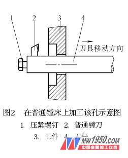
1. Process Selection and Processing <br> <br> design ideas to reduce tool procurement costs and improve the rigidity of the tool during processing, to ensure accuracy and efficiency of the hole, the hole machining NC machining center in the embodiment 2 to be taken Process method. We know that when the above two stepped holes are machined on a common boring machine, the processing method is as shown in Fig. 2. First, the 30 mm hole is cut out, and then the method of "reverse boring" is used, that is, after boring the 30 mm hole, 镗The effective part of the knife extends out of the machined hole, and then the boring tool is loosened, and the tool is reverse mounted. Through the "knocking" and "trial cutting", the effective cutting diameter of the tool meets the 45mm hole size accuracy requirement. After the tool is installed Move the spindle back at a constant speed and 镗45mm hole to the required depth (Figure 2). When processing the above holes on the CNC machining center, it can also be carried out by referring to the method of “reverse boring†holes, but in order to ensure the processing efficiency, it is impossible to adopt the same method as the ordinary boring machine, by “knocking†and “trial cutting†and Constant measurement to determine the effective cutting diameter of the tool and the 45mm hole depth. Therefore, in order to achieve efficient, high-quality, low-cost machining of the hole in the machining center, it is necessary to design a suitable sizing tool and prepare a reasonable machining process and machining program in order to "reverse" the hole in the machining center. And reflect the high efficiency and automation of the machining center.