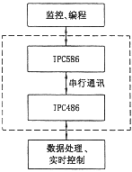
With the development of computer technology, Windows as a multi-window, multi-tasking new graphics window operating environment, has many DOS incomparable advantages. It performs parallel management of tasks, file output devices, etc., and provides powerful functions and a friendly graphical user interface (GUI). It is widely used not only as a support platform for managing transactional work, but also as an engineering project in the industrial field. Concerned by personnel. With the industrial PCs entering the field of numerical control, the development of CNC punch monitoring and programming systems is increasingly applying the latest hardware and software results of PCs. With the development of CNC technology and computer technology, in the Windows environment, the use of advanced "5C" (Computer, Control, Communication, CRT, C / C + + language) technology, the development of CNC punch monitoring and programming system has become a trend And direction. 2 The overall design of CNC punching CNC system The design of the CNC punching machine CNC system adopts the internationally popular industrial PC platform, and at the same time, it satisfies the requirements of human-computer interaction friendly and real-time control. The system adopts the structure of industrial PC dual CPU front and back, and the upper computer IPC586 and control machine The IPC486 is constructed as shown in Figure 1. The background host computer completes functions such as management, monitoring, and programming, and directly faces the user. The front-end controller completes functions such as data processing, real-time control, and status detection. Information is exchanged between the front and the back by serial communication. The application software of the CNC system includes the application software of the upper computer and the control machine, which are respectively operated in the Windows NT operating environment and the DOS operating environment, and each completes independent functions. The human-computer interaction control command of the upper computer is converted into a communication code recognizable by the control machine according to a certain communication protocol format, and transmitted to the control machine through the serial communication method, and the data processing is performed by the control machine, and the processing result is sent to the punching machine. The actual machining control is performed, and the result and the real-time running status information of the punching machine are also transmitted to the upper computer through serial communication and fed back to the user. Figure 1 CNC system structure 3 Functional requirements for monitoring and programming systems According to the overall design requirements and task division of the CNC system, the control and operational functions of the monitoring and programming system include system operation, processing file management, display management, system diagnostics, programming, system setup and management. Next page
Based on industrial PC, multi-processor structure, and development of punching CNC system in Windows environment, foreign countries have begun to develop and launch corresponding products. In order to gain a place in the increasingly competitive market, we must learn from the successful experience of foreign countries, directly apply the latest achievements of today's microelectronics and computer technology, and develop a high-performance punching CNC system that meets user requirements and functions. It has three characteristics of "advanced, practical, and commercial" to continuously enhance its competitiveness in the market. 
(1) System operation
Contains the following:
1) Automatic processing: there are reference point setting, automatic continuous processing, automatic jump selection processing, automatic starting code segment processing and single step processing;
2) Processing simulation: the same as above;
3) Manual control: including continuous feed, mold selection step, mold continuous, step feed and manual speed;
4) MDI control: refers to manual program input.
(2) Processing file management
Refers to the input and output of the processing file.
(3) Display management
Includes X, Y displacement display, tool display, part machining graphic display, I/O display, and machining program display.
(4) Diagnostic operation
Including communication error diagnosis, operation error judgment and alarm, and processing file programming error judgment.
Design of turret CNC punch monitoring and programming system under Windows environment
1 Introduction