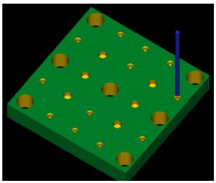
(1) Position control (positioning control) CNC machine tool Control features: Quickly move from one position to the next in the machining plane with high positioning accuracy. It is not processed when moving, and the third axis is processed after it is in place. Used for machining hole system (drilling, boring, punching), such CNC machine tools include: CNC drilling machine, boring machine, punching machine, coordinate measuring machine. (2) Line motion control CNC machine tools Control features: Control the tool or table to move and machine linearly along the parallel axis at the appropriate speed. The speed is adjustable within a certain range. It is used for machining step shafts and milling planes. These machines include: simple CNC lathes, linear control CNC milling machines. There is also a CNC combination machine tool. (3) Contouring control CNC machine tools Control features: continuous, according to a certain contact, coordinated control (linkage) two or more coordinate axes at any time of the movement position, speed and direction, so that the tool relative to the workpiece according to the required contour trajectory. Also known as continuous control or multi-coordinate linkage CNC machine tools. 1. CNC machine tool for plane contour machining Controls the linkage of two coordinate axes, so that the tool makes a plane curve motion with respect to the workpiece in a certain coordinate plane, thereby processing the contour part of the plane curve. Commonly used for turning curved surfaces and milling flat curve contour parts (planar cams). Also known as two-coordinate linkage CNC machine tools. When machining a plane profile, no matter what curve is composed of the contour, a small straight line is used to approximate the curve: Taking the milling plane contour as an example, set the current milling cutter rotation center at I/point, and the cutting point on the contour is I. In unit time, the numerical control system controls the tool to feed ΔxI simultaneously with the workpiece in the X and Y coordinate axes. And Δyi produces a synthetic linear displacement ΔLi, which is moved to point J, so that a small straight line IJ is machined on the workpiece, and the arc segment IJ is approached. Thus, the feed motion of the X and Y axes is continuously controlled, and a plurality of small straight lines can be processed. Polyline to approximate the curve outline. Here, the key to control is to determine the feed displacement components ΔxI and ΔyI per unit time, which is done by interpolation operations and tool radius compensation operations. Calculation conditions: combined feedrate, unit time length, contour curve equation, tool center offset determined by tool radius and machining margin. Next page 

Introduction of CNC machine tools (Figure)
One. According to the processing function of CNC machine tools