Development of gear precision forging technology
Abstract : Three types of automotive gears, such as cylindrical spur gears, cylindrical helical gears and synchronous gears, were studied and tested. The manufacturing process uses warm forging and cold processing, and uses finite element simulation to analyze the forging process and design the mold to ensure the accuracy of the gear. After three years of research, the basic technology has been mastered, and the next step will be to conduct on-site testing at the factory.
Key words : gear; precision forging; computer simulation; mold design and manufacturing
1 Introduction
Precision forging of gears has been greatly developed in recent decades, and more and more manufacturers and users are paying attention to the use of forging methods to manufacture gears. It is generally believed that the use of forging methods can improve the utilization of materials, increase productivity, improve the mechanical properties of gears, reduce costs and enhance market competitiveness. Especially for large-scale production in the automotive industry, precision forging of gears has greater benefits and potential [1~3].
Although precision forging of gears has many advantages and has been used for the production of bevel gears, it is still a long way from the scale production of cylindrical spur gears and helical gears of a certain size. Especially for gears used in automotive power transmission, it is necessary to establish a practical and reliable production process to be acceptable to manufacturers.
Gear precision forging technology originated in Germany. As early as the 1950s, due to the lack of sufficient gear processing machines, the Germans began to test the bevel gears by closed hot forging. The main feature is the use of a very new EDM process at the time to make the cavity of the forging die. In addition, the forging process is strictly controlled. On this basis, the gear forging technology is further applied to the production of spiral bevel gears and cylindrical gears. However, in the cylindrical gear forging, since the plastic flow direction of the metal material is perpendicular to the direction of its force, the tooth profile is more difficult to form than the bevel gear. The forging research of cylindrical gears began in the 1960s, and there was a great development in the 1970s, which was mainly under pressure from the automobile industry to reduce costs. By the 1980s, the forging technology was more mature, achieving higher precision and consistency, enabling the forged production gear to be accurately positioned on the production line, suitable for mass production.
The purpose of precision forging of gears is to directly produce gears that do not require subsequent machining. If forging can be performed at room temperature, the shape and size of the gear can be easily controlled, and the error caused by high temperature can be avoided. At present, more bevel gears and small-sized cylindrical gears have been produced in this way. When the overall size is suitable, it is also possible to manufacture cylindrical straight and helical gears by a cold extrusion process. However, most of the gears used in automobile transmissions have large diameters and heights, and are not suitable for extrusion processes. For example, closed die forging requires high pressure to allow the metal material to flow and fill the mold cavity. Therefore, such gears need to be hot forged or warm forged. The high temperature will bring about oxidation of the material, distortion of the mold, affecting the precision and surface quality of the forging. It is more difficult to correct these errors with additional machining and increase the cost. In particular, when a subsequent grinding process is used to correct the error in the tooth profile, in addition to increasing the cost and extending the man-hour, there is also a problem of positioning of the gear in the grinding process.
At present, the more consistent process routes are the combination of hot forging, warm forging and cold forging. Hot forging and warm forging can achieve high efficiency and high utilization of materials. The cold forging process corrects errors in hot and warm forging processes and improves surface quality. At the same time, the cold treatment process can also obtain residual compressive stress on the tooth surface and improve the life of the gear.
While working at the University of Birmingham, the Institute of Mechanical Engineering has just completed a project funded by the British Engineering Research Association (EPSRC) and seven companies in the UK (gear manufacturing, mold making, gear users, forging plants and steel companies). Three-year research project of cooperation: precision forging of cylindrical spur gears and helical gears. Based on years of research and practice, the project further explores the mechanism of gear forging, using modern analytical methods, such as computer simulation and design techniques, to develop a production and economically viable forging technology that is manufactured in the tooth. Precision gears that are no longer needed for subsequent machining. The project studied and tested three types of gears: cylindrical spur gears, cylindrical helical gears and synchronous gears. Considering the economics of the whole process, precision forging is limited to the contour part, while the tooth end and the inner hole are cut. The manufacturing process is warm forging and cold processing, and the gears satisfying the shape requirements are obtained by warm forging, and a margin of about 011 mm is left in the contour portion. In the cold treatment process, the warm-forged gear is extruded through a precision designed and manufactured mold to correct the error of the contour portion and obtain a highly accurate toothed surface. During the research process, the finite element method was used to analyze the forging process and design the mold to ensure the accuracy of the gear. After three years of research, the basic technology has been mastered, and the next step will be to conduct on-site testing at the factory. At the same time, it is preparing to declare the second phase of the project.
2 warm forging process
As the project required to find a practical production route suitable for the factory, the study selected a high-speed, single-acting single-crank mechanical press. Since the forging is heated, the thermal expansion and cold shrinkage of the material and the deformation of the mold must be considered, for which finite element is used for accurate calculation. In addition, the finite element is used to simulate the forging process to ensure the forging accuracy. Experiments have shown that forging steel gears between 850 °C and 950 °C, the error can be controlled within the range of 0105mm.
Hollow cylindrical billets are commonly used for the forging of hollow axisymmetric parts or gears. Figure 1 shows the design of a closed die forging of a cylindrical spur gear. The right side of the figure shows the situation before forging, and the left side shows the situation after forging. The mold consists of an upper die (punch), a lower die (reverse punch), a mandrel and a contoured cavity (as shown). The mold cavity portion is supported by a spring. During the forging process, the punch moves downward along with the press slider and drives the mold cavity downward. Since the punch only needs to seal the upper surface of the cavity and does not need to be pressed into the cavity, the punch can be made into a simple shape. In this design, the punch is in the shape of a stepped cylinder. The reverse punch remains stationary during the forging process and the gear is ejected out of the cavity after forging. The mandrel is here integrated with the punch to aid in the positioning of the blank. Since the cavity moves with the forging during the forging process, the friction between the cavity and the forging will contribute to the metal flow and the required load is also lower than when the cavity is fixed.
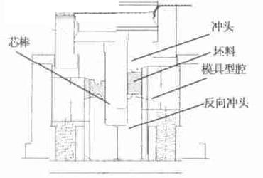
Fig.1 Design of closed die forging of cylindrical spur gear
Next page
What`s in a mounting system?
Solar Mounting Systems are composed of three parts: (1) roof attachments, (2) mounting rails, and (3) module clamps.
Each of these components can vary in size, weight, and material, so manufacturers typically provide detailed information to aid in component selection and system design.
Some manufacturers even offer free online design tools to help with planning.
The Series 100 Roof Mount System boasts unique, pre-assembled, stainless steel [Snap-In" hardware and watertight flash attachments. This system is installed with a single tool. No cutting or drilling means less rail waste. It is fully integrated with built-in wire management, solutions for all roof types, one-size-fits-all features, and can withstand extreme environmental conditions. Series 100 is listed to UL Standard 2703 for Grounding/Bonding, Fire Classification and Mechanical Loading. UL 2703 Certification and Compliance ensures that SnapNrack installers can continue to provide the best in class installations in quality, safety and efficiency.
* Appealing design with built-in aesthetics
* No grounding lugs required for modules
* All bonding hardware is fully integrated
* Rail splices bond rails together, no rail jumpers required
* No drilling of rail or reaching for other tools required
* Class A Fire Rating for Type 1 and 2 modules
Solar Mounting Products,Solar Panel Installation,Solar Mounting Systems
Yangzhong Huaxin Power Equipment Co.,Ltd , http://www.huaxinbusbarchina.com