An oscilloscope is a widely used electronic measuring instrument. With the rapid development of electronic technology, various types of electrical signals are becoming more and more complex. In engineering applications, the real-time sampling rate and waveform capture rate of signals are also high. Digital oscilloscopes are essential for hardware development and test personnel in various positions. tool. Aiming at the needs of current flexible industrial measurement systems, this paper presents the scheme of DSP+CPLD, which realizes the design of a high-precision, high-integration portable digital storage oscilloscope. The system uses digital integrated circuits as much as possible, and the structure is simple and the measurement results are obtained. High reliability, friendly human-machine interface, high sampling rate, high resolution and low error. 2.3 Amplitude Signal Acquisition In order to meet the acquisition of high-frequency signals, the AD7667 from Analog Devices is used to measure the amplitude of the signal under test. The AD7667 is a 16-bit A/D converter with an internal 2.5 V reference. The operating range is 0 to 2.5 V, the LSB is less than ±2 b, the conversion rate is 800 Kb/s, and the conversion time is less than 1 μs. It is powered by a single +5 V supply. . The signal conversion circuit converts the measured signal into an effective value in the working range to perform accurate measurement. The method of extracting the equivalent time sampling can improve the sampling rate, but requires the repetition frequency fi of the input signal to be controlled by the accuracy, and the equivalent sampling rate is Dfs, independent of the input signal, when the repetition frequency of the input signal deviates (2 In the value given in , the equivalent sampling degree becomes the maximum time deviation: Equivalent to broadening the frequency band. At this time, the width of the frequency band is almost independent of the speed of A/D conversion and the speed of the microprocessor. In this way, the frequency and amplitude of the high frequency signal are easily measured by combining the designed digital oscilloscope. . Knitting Machine Rolling Takedown System Knitting Machine Rolling Takedown System,Knitting Winding System,Take Down Rolling System,Takedown Unit For Circular Knitting Machine Changzhou Longfu Knitting Co., Ltd. , https://www.circularmachine.com
1 system design
The digital oscilloscope is mainly composed of two parts: measurement control and display output. The input signal is processed at the front end of the measuring circuit and processed into an equivalent signal that can be processed by each secondary unit via the signal conversion circuit. The comparison circuit processes the output of the square wave and the equivalent operational amplification output signal with a peak-to-peak value of 2.5 V. The square wave signal acts as a counting pulse, triggering the programmable logic device CPLD to measure the frequency value. At the same time, the signal outputted by the operational amplifier is input to the sample-and-hold, and the main controller DSP issues a latch signal to its associated pin to implement the function switching of the sampling and latching output of the signal to be tested.
When the control terminal is set to "1", it is a latched output. At this time, the output signal can be used for data acquisition by the A/D converter device; when "0" is set, the signal acquisition is realized. The data collected by the A/D is sent to the DSP, and then the DSP first stores the external data in the external memory, and then analyzes. Finally, the processed data is sent to the liquid crystal display through the RS 422 standard interface in the form of a data packet. Output.
2 hardware design
The hardware part of the system is composed of a signal input conversion circuit, a sample and hold circuit, a main control circuit, and an intelligent terminal device.
2.1 Signal input conversion and sample and hold circuit The signal input conversion circuit is mainly used to realize the equivalent conversion of the signal. The design uses high-speed OP37 for signal conversion, sample and hold, which is an important part of the data acquisition system, which acts as an isolation buffer for the signal. If A/D conversion is required for analog signals with high speed, the conversion accuracy is relatively high. In order to prevent signal changes during A/D conversion, S/H circuits must be used. The S/H circuit and A/D cooperate to eliminate the output ripple of the A/D and implement multi-channel sampling control through the MUX.
The high-performance single-chip sample/hold LF398 is used here, which has high DC accuracy, fast sampling time and low drop speed. The dynamic performance and retention performance of the device can be optimized by suitable external holding capacitors. The signal conditioning circuit is shown in Figure 2.
2.2 Frequency Measurement Circuit The oscilloscope's frequency measurement is based on the principle of an equal precision frequency meter. Completed by the programmable logic device EPF10K50V, the standard frequency signal of 100 MHz directly enters the EPF10K50 V. The device uses the square wave pulse output from the signal input conversion circuit as the clock input signal of the counter, counts it with a standard 100 MHz, and finally calculates the frequency of the input signal.
The EPF10K50V is programmed by the graphic method and the VHDL language. In this design, the CPLD completes the measurement of the signal frequency. The frequency measurement principle is as follows: the measured signal count value is Nx in the unit measurement time Tp, and the count value of the standard signal is Ns. On the basis of the known standard frequency fs, the measured signal frequency value fx satisfies: 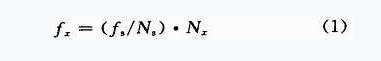
2.4 Human-Computer Interaction Part Design The display and command input of the oscilloscope is realized by the intelligent terminal device LJD-ZN-3200K. LJD-ZN-3200K is an intelligent graphical interface output device with input and output as one. The resolution is 640×480, which can meet the requirements of system design. The device terminal communicates with the main controller through the serial interface to complete data transmission.
The touched control input can be realized by loading the designed graphical interface into the intelligent terminal storage unit and then identifying the coordinate values ​​according to the settings. The oscilloscope has a total of 9 function keys, namely: 3 vertical discrimination selection buttons for vertical sensitivity selection; 3 horizontal discrimination selection buttons for horizontal scanning speed selection; sampling mode switching buttons for selecting real-time sampling and Equivalent sampling; waveform storage button and waveform callout button for current waveform acquisition, storage and recall; single trigger button for single acquisition and storage of signals that meet trigger conditions.
3 signal acquisition and processing analysis
3.1 Signal Acquisition Principle Selecting reasonable sampling methods for different frequency signals will directly affect the measurement accuracy of the system. In digital signal analysis technology, there are two commonly used signal sampling methods: real-time sampling and equivalent sampling.
Real Sampling is usually of equal time interval. The highest sampling frequency is the Nyquist limit frequency. The characteristic is that the duration of the pulse sequence sampled by one waveform is equal to the time actually experienced by the input signal, so the spectrum of the sampled signal. More than the original signal. In this design, the A/D converter frequency is 400 kHz. According to the sampling characteristics, the digital oscilloscope can sample and output the input signal of no more than 50 MHz.
Equivalent Sampling is a feature of time-domain repetition of a periodic signal. Multiple lower sampling rates are sampled at different time periods, and then these low sampling rate samples are combined into high sampling rate data samples. Therefore, the data acquisition method of the original signal waveform is reconstructed. It uses the periodicity of the signal to reduce the pressure on the high-speed sampling circuit at the expense of increasing the acquisition time, and restores the original signal through recombination.
In this paper, we extract the equivalent sampling time sampling, which uses the special relationship between the repetition frequency fi of the signal and the sampling rate fs, so that the equivalent sampling rate is increased by D times.
First, the repetition frequency fi of the input signal is appropriately selected, the signal waveforms of the D periods are sampled, and then the recorded data is rearranged and combined by a simple algorithm to obtain a complete input signal waveform, so that the equivalent sampling rate is the actual sampling. The rate is D times.
In actual implementation, the selection of D depends on the required equivalent sampling rate fe, so that fe=Dfs can be. Where L is the number of actual sampling points in a single cycle, L = int (M / D), M is the sum of the recorded sample data. The repetition frequency of the output signal is: 

Finally, the sampled data is stored, and then a unified analysis is performed to reproduce the function curve of the signal, and the amplitude can be calculated.
Since the voltage signal sampling analysis is equivalent in the design process, the discrete sequence with time as the independent variable is collected. The sampled data reflects the change process of the measured parameter, but with a certain degree of error. It is bound to cause distortion of the collected data. In order to avoid the interference of the values ​​within the allowable range of non-error to the measurement results, the software is used to modify the data by curve fitting the measurement results to ensure the relative accuracy of the measurement results.
3.2 Display resolution calculation The waveform display window has a total of 354x446 image elements, which can meet the design requirements, analyze the collected data uniformly, and use sine interpolation algorithm to process the corresponding output and reproduce the measured signal waveform.